A Guide to Fire Alarm System Design.
The following BS5839 fire alarm system design guide can be downloaded here for your convenience:
PDF version of the guide
WELCOME
This fire alarm system design guide has been developed to highlight the key points of the latest version of the standard:
BS5839 Fire detection and fire alarm systems for
buildings – Part 1 2017: Code of practice for design,
installation, commissioning and maintenance of
systems in non-domestic premises.

The guide should not be used as a substitute for the standard.
This guide will be of particular interest for those designers and installers that need simple guidance to the selection, spacing and location of fire devices.
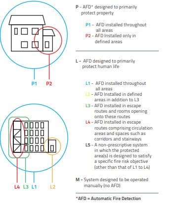
CATEGORIES
Fire Alarm and Fire Detection systems are categorised in the following way:
SMOKE DETECTORS
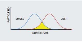
It should be noted that large smoke particles will have a similar particle size to small particle contaminates including some types of dust and aerosols. As such care should be taken when siting smoke detectors to limit subjection to this phenomenon.
HEAT DETECTORS
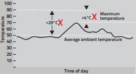
The minimum static response of heat devices should not be less than 29°C above the average ambient temperature or less than 4°C above the highest temperature the device can be expected to experience.
FIRE DETECTOR COVERAGE & POSITIONING
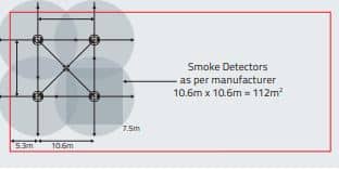
Smoke detection devices have an individual coverage of 7.5m radius. However, these radii must overlap to ensure there are no ‘blind spots’. Therefore the individual coverage can be represented by a square measuring 10.6 x 10.6m giving an actual area coverage of 112m² per device.
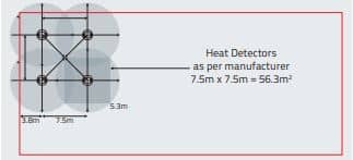
Heat detection devices have an individual coverage of 5.3m radius. However, these radii must overlap to ensure there are no ‘blind spots’. Therefore the individual coverage can be represented by a square measuring 7.5 x 7.5m giving an actual area coverage of 56.3m² per device.
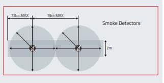
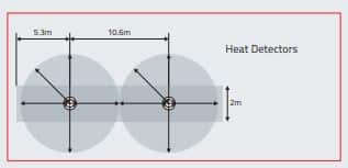
In corridors less than 2m wide the horizontal spacing of detectors may be increased, the areas of coverage need not overlap as in the case of a room. Any corridor over 2m wide is deemed a room and device spacing should follow the standard for rooms (see above).
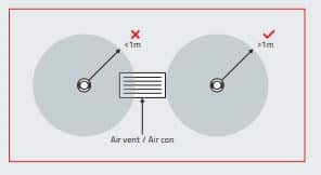
Detectors must not be sited less than 1m from air inlets or air conditioning units.
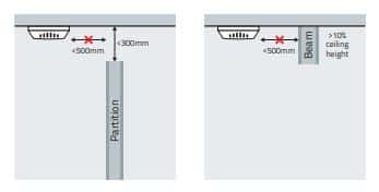
A device should not be mounted within 500mm of any obstruction. If the top of a solid partition is less than 300mm from the ceiling then treat it as a wall. Similarly, ceiling obstructions such as beams should be treated as walls if deeper than 10% of the ceiling height.
SMOKE DETECTORS
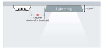
Never mount devices closer than twice the depth of light fittings.
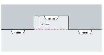
Voids less than 800mm in height need not have independent coverage unless fire or smoke is able to spread from one area to another through the void or risk assessment shows AFD (Automatic Fire Detection) to be necessary.
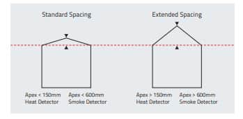
For ceilings that feature an apex: as long as the height of the apex from the rest of the ceiling is less than 150mm for heat detectors or less than 600mm for smoke detectors then these can be treated the same as flat ceilings. For higher apexes, a device should be installed at the highest point. The distance to adjacent devices can be increased by 1% per degree of angle of the roof up to a maximum of 25%.
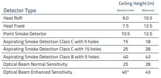
*Supplemented detection recommended unless the risk of stratification is minimal.
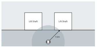
Vertical shafts like lifts and stairways should have a device mounted within 1.5m of any opening.
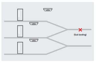
Enclosed stairways should have a detector on each main landing.
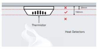
The sensing element of a heat detection device (thermistor) should not be less than 25mm below the ceiling, and not greater than 150mm below the ceiling.
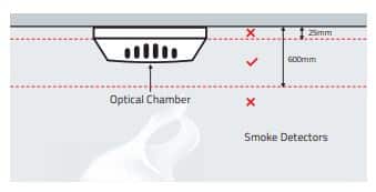
The sensing element of a smoke detection device (photoelectric smoke chamber) should not be less than 25mm below ceiling, and not greater than 600mm below ceiling.
SEARCH DISTANCE
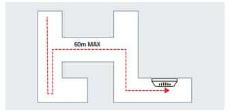
A person searching a zone for a fire should not have to travel more than 60m from the entrance of a zone to identify the source of a fire. Particular attention is required when sighting the detectors LED to minimise the search.
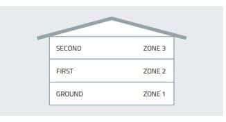
Less than 300m2 can be covered by a single zone. When the total floor area exceeds 300m2, each floor would require a zone (or zones if the floor area exceeds 2000m2 ). Stairwells, liftwells or similar should be separate zones.
Zones should not cross floors.
MANUAL CALL POINTS (MCP)
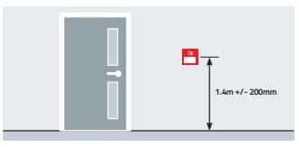
The centre of the element of the manual call point should be positioned 1.4m (+/-200mm) from floor level (unless a wheelchair user is likely to be the first person to raise the alarm, when this is applicable it should be noted on any certification). All manual call points should be fitted with a protective cover, which is moved to gain access to the frangible element.
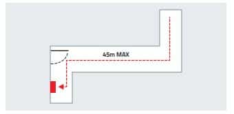
A person should not have to travel more than 45m along an escape route to reach a manual call point (25m if disabled person to operate, or rapid fire development is likely). Manual call points should be sited at all stairwells and exits from the building.
SOUNDERS
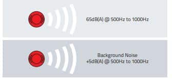
The minimum sound level of a sounder device should be 65dB(A) or 5dB(A) above a background noise which is louder than 60dB(A) (if lasting more than 30 seconds) and at a frequency of between 500Hz and 1000Hz. The maximum sound level should not be greater than 120dB(A) at any normally accessible point. Sounder volume may be reduced to 60dB(A) in stairways, enclosures up to 60m and specific points of limited extent.
Sounder device cabling should be arranged so that in the event of a fault at least one sounder will remain operational during a fire condition.
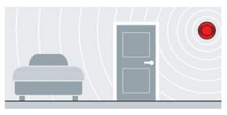
For areas where people are sleeping, sounder devices should produce a minimum of 75dB(A) at the bed-head with all doors shut.
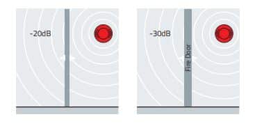
Decibel loss occurs through doors. Approximately -20dB(A) through a normal door, and approximately -30dB(A) through a fire door.
VISUAL INDICATION DEVICES
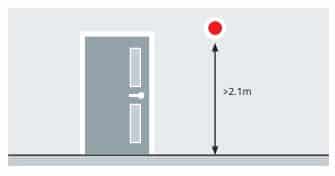
Visual indication devices (VIDs), such as strobes, can be ceiling or wall-mounted. For wall mounting, they should always be mounted 2.1m above floor level. Visual alarm devices should conform to BS EN 54-23.
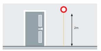
Unless MICC cable is used, all cabling should be mechanically protected from floor level up to a height of 2m.
VISUAL ALARM DEVICE CATEGORIES
EN54-23 specifies that the VAD produces an illumination of 0.4 lux on surfaces perpendicular to the direction of the light emitted from the device. They are not designed to wake people that are asleep and can be red or white light.
VADs are classified into three categories based on their application:
W – Wall-mounted
C – Ceiling-mounted
O – Open Category
Wall and Ceiling mounting categories are specified at specific installation heights and particular patterns of coverage – see diagrams. For W and C categories, the shape of the volume covered is fixed by the standard. The dimensions of this coverage volume are specified by the manufacturer. For all categories, the volume covered can be used to determine VAD spacing within the building. Open category allows manufacturers to specify the coverage shape and volume and does not put any restriction on mounting height.
Wall-Mounted – Coverage Volume
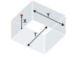
Wall-mounted VADs cover a cuboid volume with a square floor area. The coverage volume is presented as a code in the form of W-X-Y, where W is Wall-mounted, X is the max mounting height (m) and Y is the width and length (m) of the coverage floor area. The min mounting height is 2.4 m.
E.g. : W-2.4-12 means it should be mounted at 2.4m from the floor and will cover an area of up to 12 by 12m.
Ceiling-Mounted – Coverage Volume
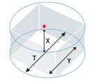
Ceiling-mounted VADs cover a cylindrical area. The coverage volume is presented as a code in the form C-X-Y, where C is Ceiling-mounted, X is the max mounting height (m) and Y is the diameter (m) of the coverage volume’s floor area. The max mounting height can only be specified as 3, 6 or 9m.
E.g. : C-3-15 means it can be mounted up to 3m from the floor and will cover a cylindrical area of least 15m diameter.
CABLING
Fire resistant cabling is now required within the whole fire alarm system including the main supply cables. The use of non-fire resisting cables, whether mechanically protected by fire-resisting construction or not, will no longer comply with BS5839.
To avoid mechanical damage and electromagnetic interference, fire alarm cables should not be installed in the same conduit as the cables for other services. Where fire alarm cables share common trunking, a compartment of the trunking, separated from other compartments by a strong, rigid and continuous partition reserved solely for fire cables should be implemented.
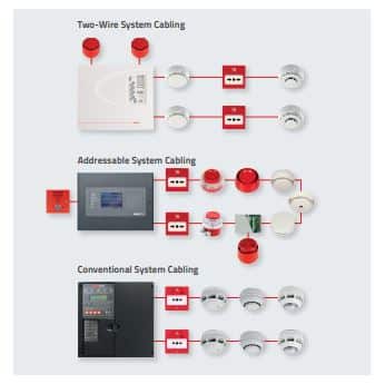
FIRE DETECTION & ALARM SYSTEMS
2-Wire Fire Alarm System
A conventional 2-wire fire alarm system is often the natural choice for smaller applications or where budget constraints exist.
ESP’s MAGDUO 2-wire fire alarm system has long been known for its adaptability and cost-effectiveness within a variety of applications, big or small … making it one of the most flexible products on the market.
Building on those strengths and designed for ease of use and state-of-the-art monitoring, the LPCB-Approved MAGDUO2 is the next generation in 2-wire fire alarm reliability.
The Reliable Fire Protection System You Can Count On
This versatile fire alarm system incorporates ESP’s ASD Multipoint detector using smoke and heat detection with optional built-in sounder, allowing the whole system to be installed using only one pair of wires per zone. That means easier, faster installations AND cost savings.
FIRE DETECTION & ALARM SYSTEMS
Addressable Fire Systems
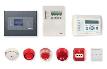
Each device connected to an addressable system has it’s own unique address. When a fire is detected the devices address is identified by the panel, pinpointing the exact location of the fire.
With a conventional system there is no way of pinpointing the exact location of the device that has been activated by a fire, only the general zone.
For example if you have a three storey building each floor may be wired as a zone, so in the event of a fire you would only be alerted that the fire was on a particular floor, not the exact location or room. This could slow down the extinguishing of any fire causing a greater risk to loss of life and damage.
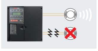
Addressable systems are wired in a continuous loop rather than radial circuits used for conventional systems. This means if the cable was to be severed on an addressable system, signals can still be transmitted to devices from either end of the loop.
FIRE DETECTION & ALARM SYSTEMS
Conventional Fire Systems
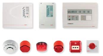
Although conventional fire alarm system cost less to purchase, they are generally more expensive to install.
This is due to each zone for detectors and call points having to be wired, on a radial circuit back to the panel.
This benefit of an addressable system is that all devices can be connected to the same continuous loop, reducing cabling and time.
Addressable fire panels have large benefits over conventional, due to the ability to continually monitor each of the installed devices individually.
The panel can determine whether each device is functioning correctly and also ascertain the amount of heat or smoke that the device is currently sensing. This technology allows the panel to make ‘intelligent’ decisions as to the appropriate action to take based on the information it receives from the individual sensors. This prevents the occurrence of false alarms which can be costly to a business.